GITALLER switch shaft circuit board replacement tutorial
GITALLER switch shaft circuit board replacement tutorial
Section titled “GITALLER switch shaft circuit board replacement tutorial”Difficulty: 2/5 | Estimated time: about 15-20 minutes
Shaft circuit board types
Section titled “Shaft circuit board types”| Circuit board | Suitable for |
|---|---|
| Golden switch shaft circuit board | 3-finger players |
| Brown switch shaft circuit board | 4-finger players |
Replacement tutorial
Section titled “Replacement tutorial”-
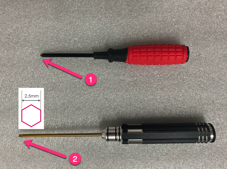
Prepare tools
Prepare Phillips screwdriver (preferably magnetic) + 2.5mm hexagon socket screwdriver.
-
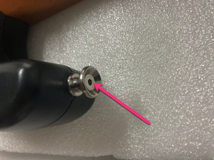
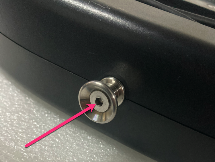
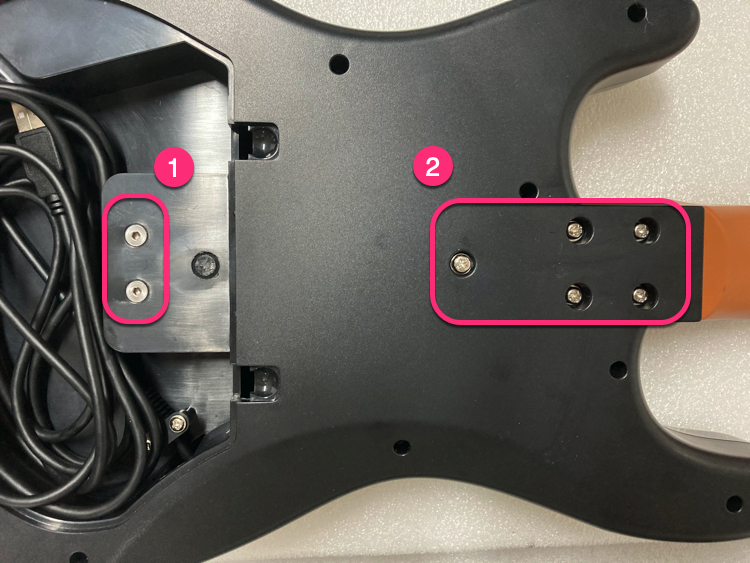
Loosen strap screws
Loosen 2 screws at the strap position with 2.5mm hex driver (just loosen, do not remove).
-
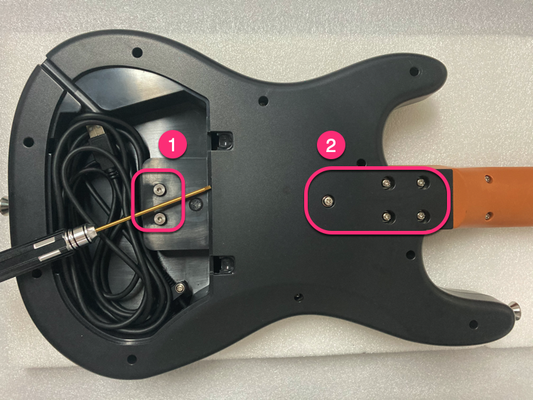
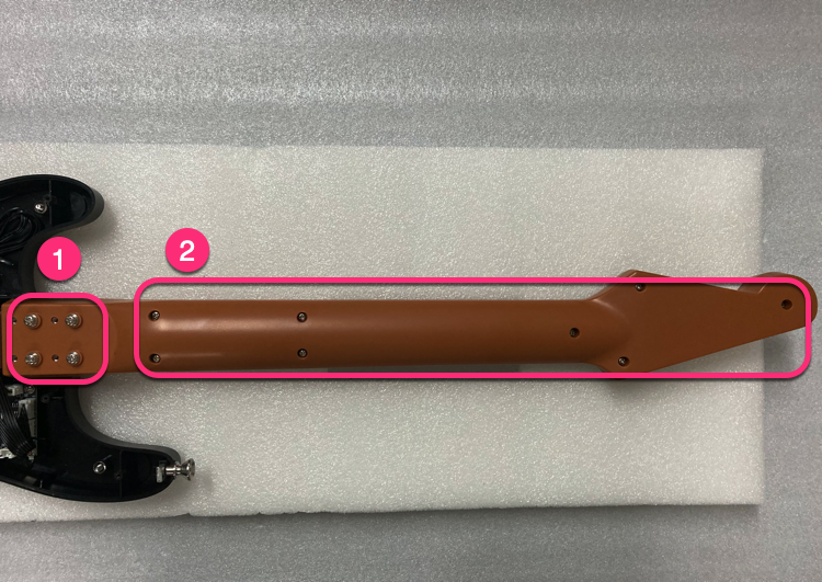
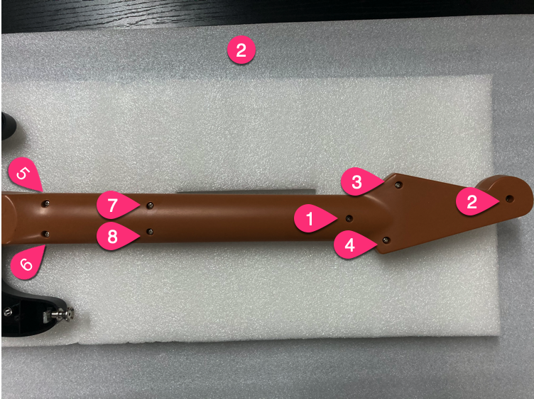
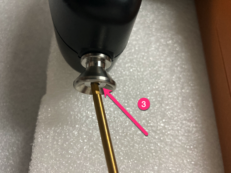
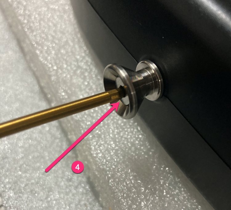
Unscrew in order
Unscrew screws in the order shown.
-
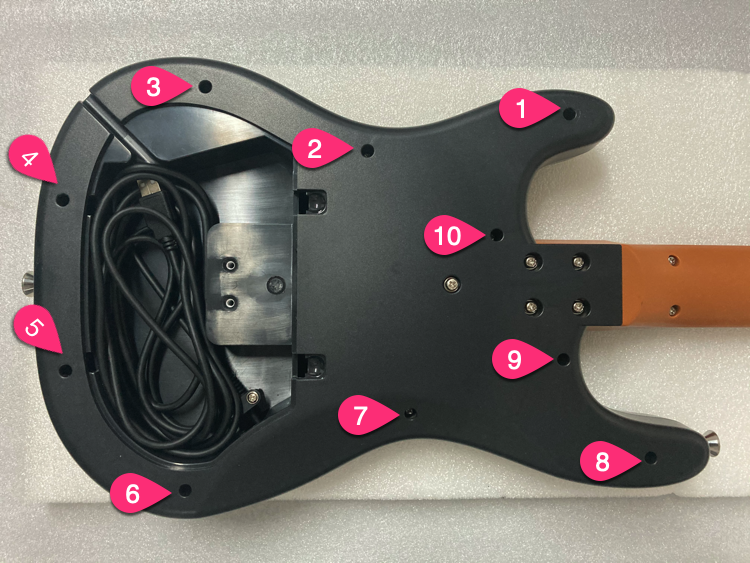
Unscrew 10 screws
Unscrew 10 screws.
-
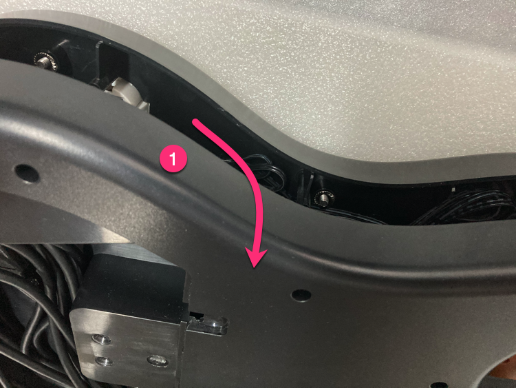
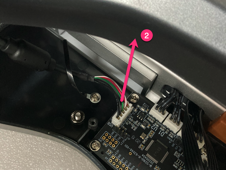
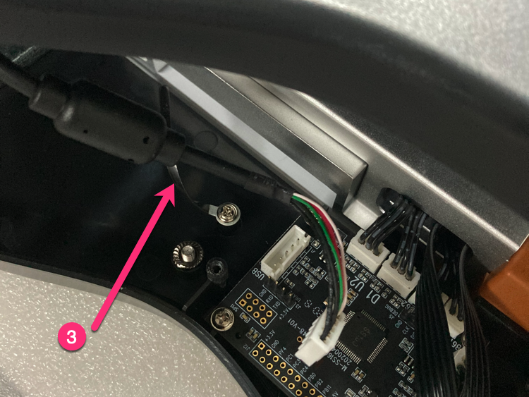
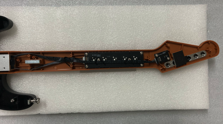
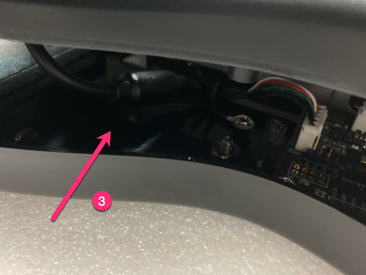
Open bottom cover
Open from the upper part, unplug the 5PIN USB cable, loosen the USB cable clip.
-
Remove screws in order
Remove screws in the order shown.
-
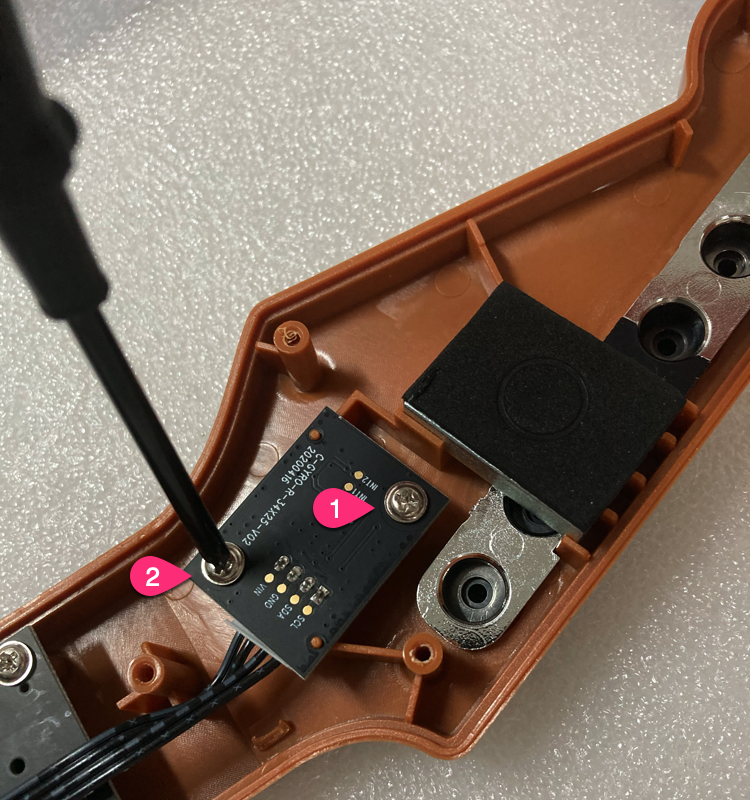
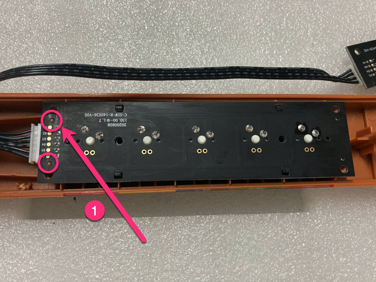
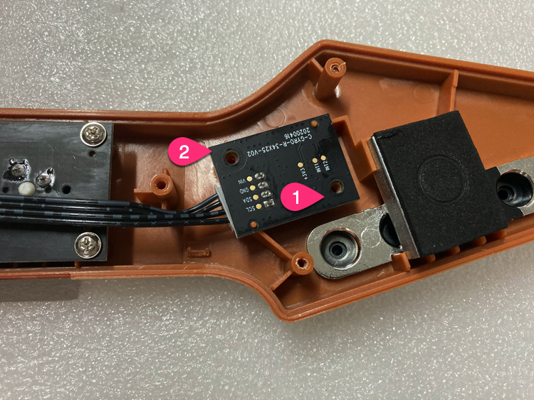
Unscrew gyro PCB
Unscrew 2 screws of the gyro PCB.
-
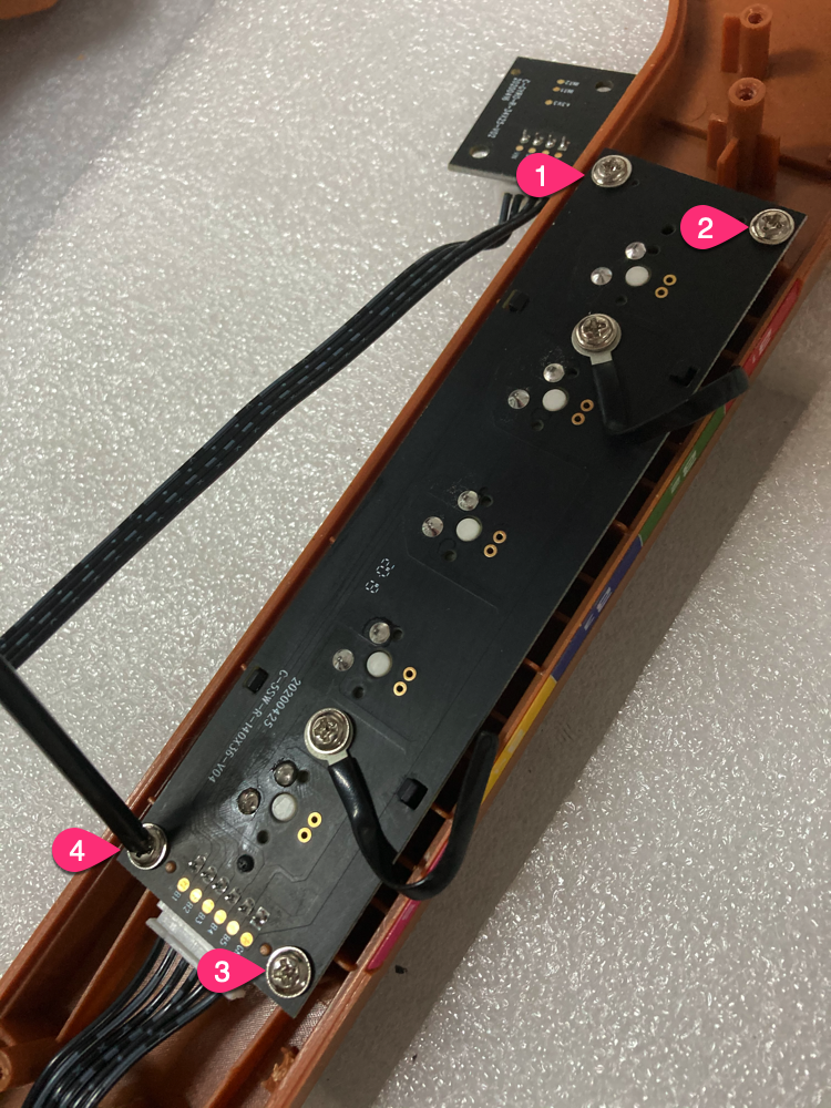
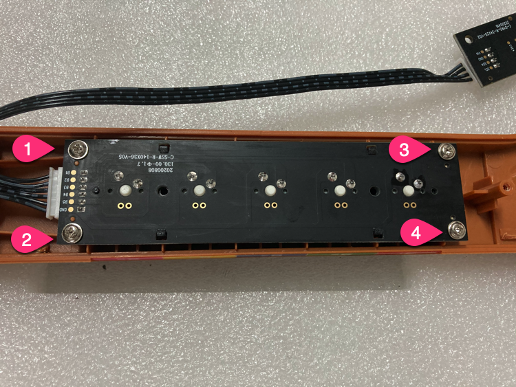
Unscrew shaft PCB
Unscrew 4 screws of the shaft PCB.
-
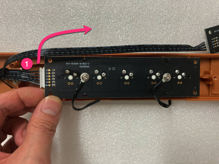
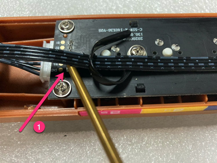
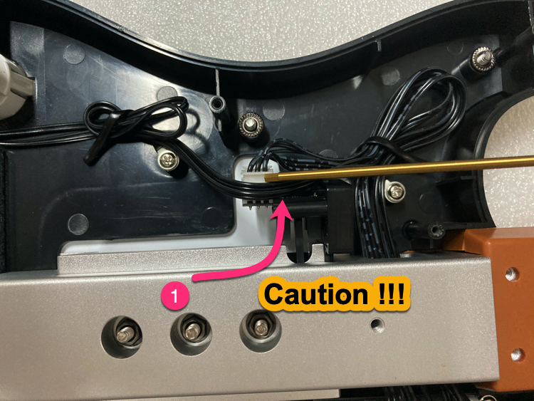
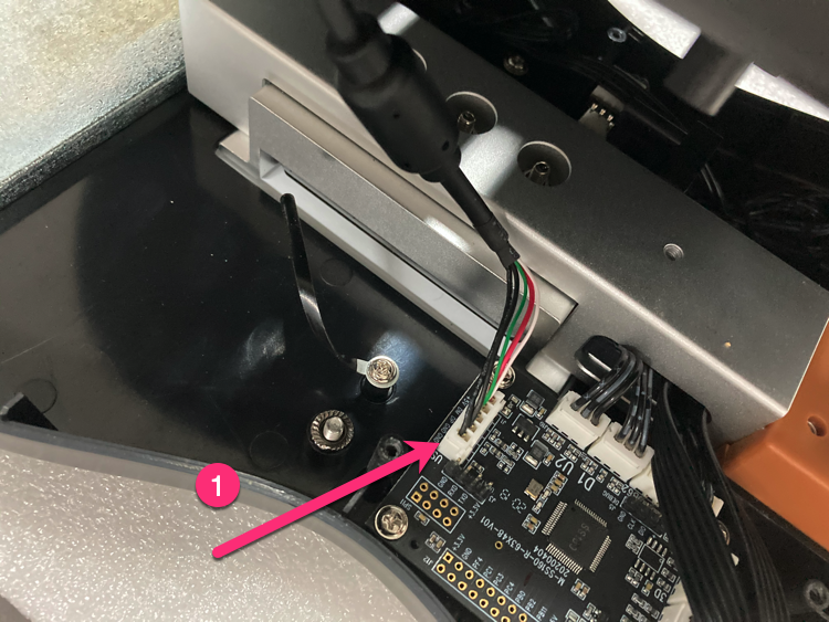
Take out shaft PCB
Take out the shaft PCB and remove the 6PIN wire (push upward).
-
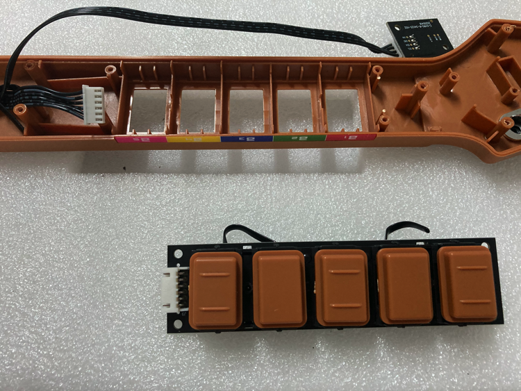
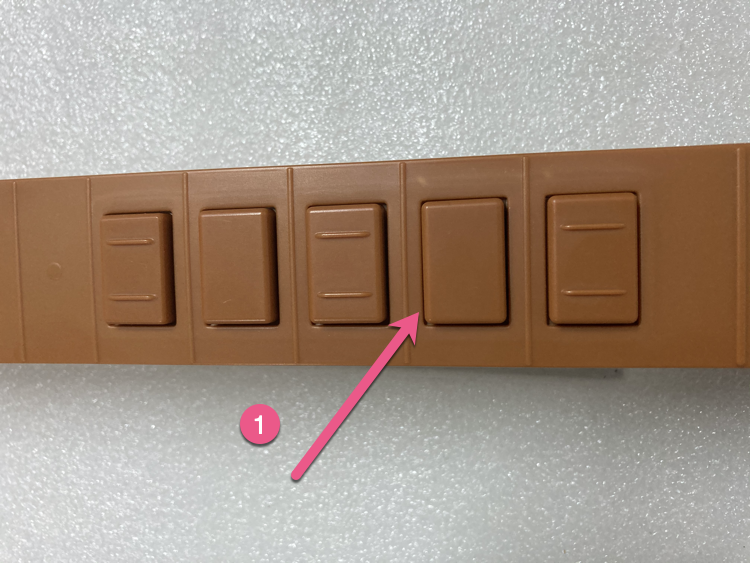
Remove keycaps
Remove all keycaps.
-
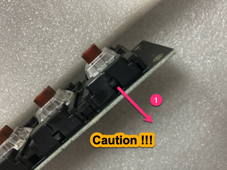
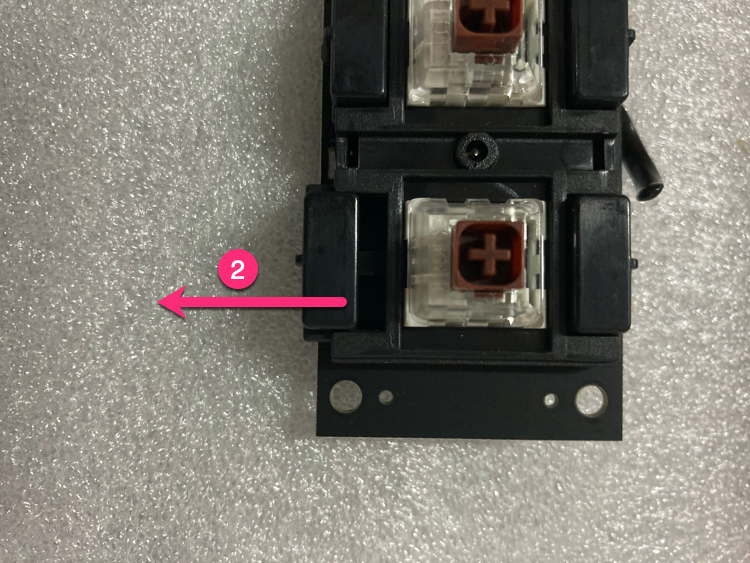
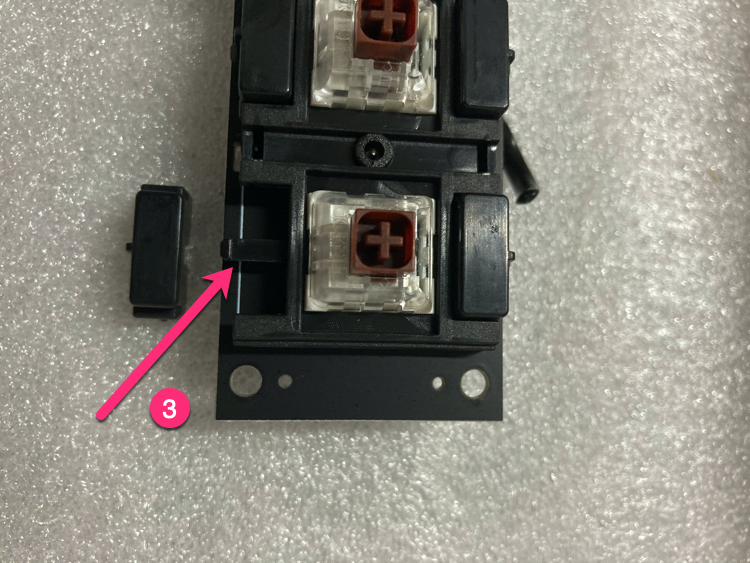
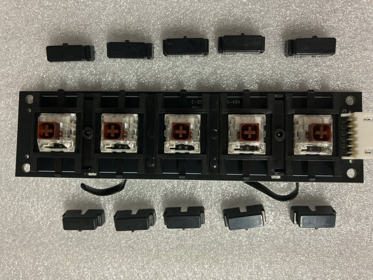
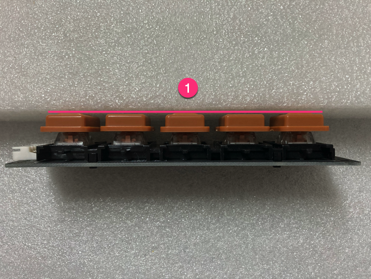
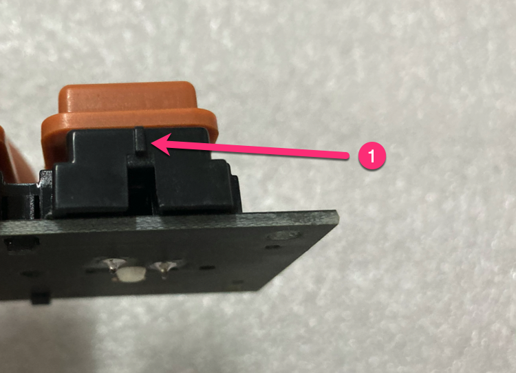
Remove limit blocks
Remove 10 limit blocks (push finger down about 1mm gently, push laterally).
-
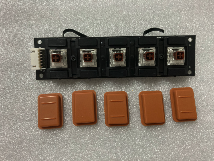
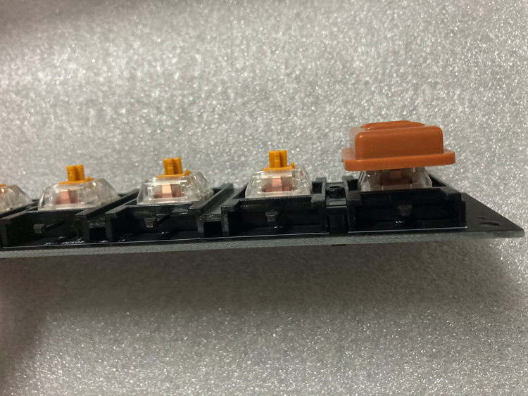
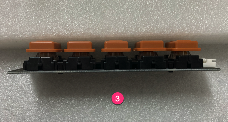
Install keycaps to new PCB
Install keycaps to the gold switch shaft PCB, check that all 5 keycaps are the same height.
-
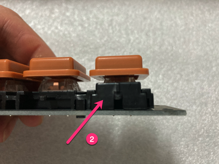
Install limit blocks
Install limit blocks (pay attention to direction).
-
Install gold switch shaft PCB
Install the gold switch shaft PCB (leave 0.2mm gap for fine adjustment).
-
Install wire harness
Remove screws from the original PCB, install on new PCB.
-
Install gyroscope PCB
Install the gyroscope PCB.
-
Fix wire position
Use wire harness to fix wire position (leave gaps between wire and DIP pad).
-
Install screws
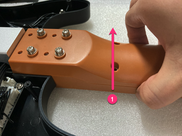
Install screws (lift guitar neck gently to make it easier).
-
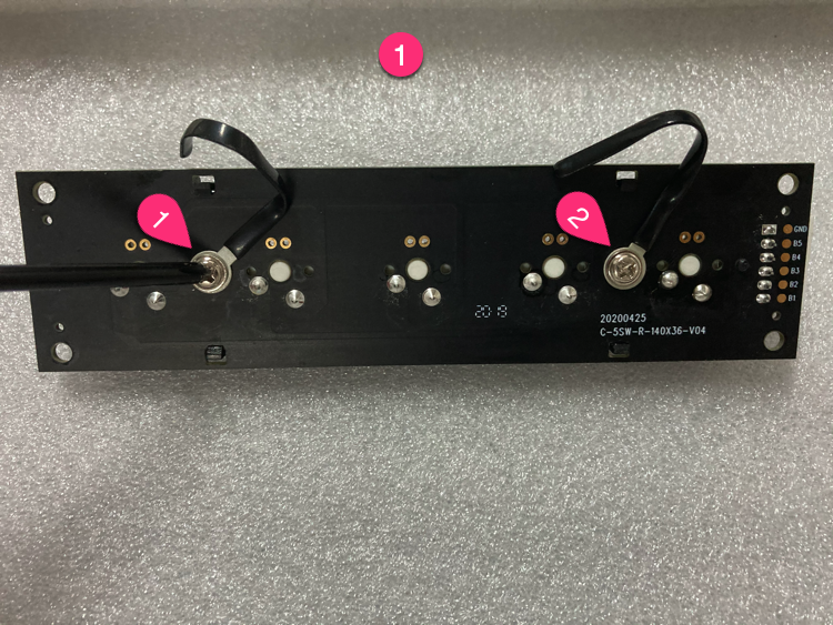
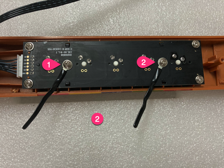
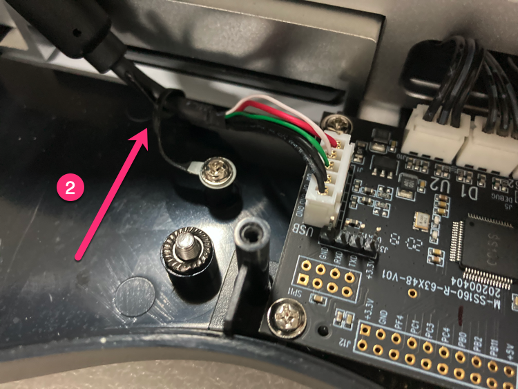
Handle button wires
Handle Select/Start button wires as shown.
-
Handle bottom cover
Insert 5PIN USB, arrange wire harness.
-
Install bottom cover screws
Bottom cover screws in order (screws 3 & 4 should not be tightened too much).

-
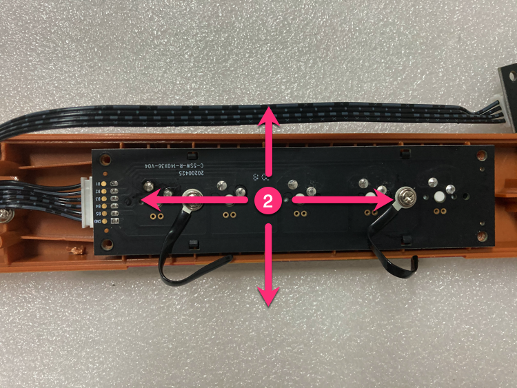
Fine-tune (if needed)
If button friction is too large: keep gaps uniform, adjust shaft PCB (0.2mm in 4 directions).
-
Done
Replacement complete, test all buttons to ensure they work properly.
© 2026 GAMO2 Docs